Van Air Systems
Van Air F200-1250-3 Filter Housing - 3" - 1,250 CFM

- SKU:
- F200-1250-3
- MPN:
- 84-23801
- Availability:
- Typically 3 - 5 Days

Description
The Van Air F200-1250-3-(Grade)-MD-PD6 Filter Housing is good for 1,250 SCFM at 100 PSIG and has 3" NPT connections. The filter element and manual drain valve are included in the price.
All Van Air F200 Series filter housings are cast aluminum and epoxy powder-coated to resist corrosion. The filter head also includes a pop-up pressure-differential indicator as standard. This differential indicator visually indicates when the filter element needs replacement. With 14 housing sizes, 9 filtration grades, and a maximum working pressure of 250 PSIG at 225° F, our F200 Series filters will meet the most unique and demanding requirements.
Van Air F200 Series compressed air filter housings are available with automatic or manual drainage. All F200 Series housings are equipped with a ball type manual drain valve as standard equipment. However, a Van Air automatic drain valve can be installed to drain the filter automatically as needed. This will prevent the filter housing from flooding, which can damage the filter element and contaminate the air system. Additional accessories for the F200 Series compressed air filter housings include additional differential pressure indicators, wall-mounting kits, and connector kits.
- Flows up to 1250 SCFM at 100 PSIG
- 3" NPT
- Maximum working pressure, 250 PSIG at 225°F
- Push-on filter element (included) for quick servicing
- Pop-up differential indicator signals when the element needs replaced
- Long-lasting elements reduce maintenance costs
Van Air has specialized in compressed air purification for over 60 years. Their compressed air filters have become an industry leader in protecting compressed air dryers, equipment, instrumentation, and processes. Van Air F200 Series compressed air filter housings have set the bar in quality and efficiency to meet today's air filtration needs.
Capacities
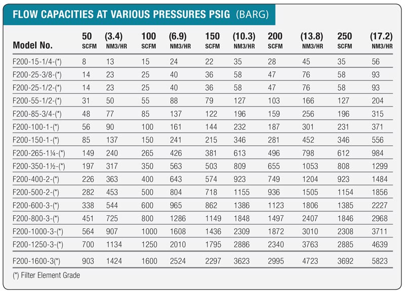
FLOW CAPACITIES - SCFM
SELECTING A FILTER
To select the appropriate filter, determine the following conditions regarding the filter installation site:
- Maximum flow rate
- Min. and Max. operating pressures
- Operating temperature
- Pipe size
- Degree of filtration desired
- Contaminants to be removed
Next, refer to the Flow Capacities chart above and locate the column with your lowest operating pressure. Then find the flow rate closest to, but greater than, that of your system. Finally, read across to the left-hand column to determine the filter model that will meet your needs.
You will now need to refer to the Filtration Grades chart, located on the next "Tab". Determine the element grade that meets your needs. Be sure that the maximum inlet temperature listed on the chart is sufficient for your operating conditions.
Refer to the Dimensions and Specifications chart on the last "Tab" above and locate the proper filter model number. Once you have located the model number within the chart, verfiy that the inlet and outlet connections are suitable for your piping. Also make sure that there will be adequate clearance for element replacement.
Filter Grades
| Application | Element Grade |
Purpose | Nominal Particulate Removal |
Element Flow Direction |
End Cap Color Code |
| Aerosol Removal (Liquids) |
AA | Extra Coarse Coalescing | 25.0 m | IN / OUT | Black |
| A | Coarse Coalescing | 5.00 m | IN / OUT | Green | |
| B | General Purpose Coalescing |
1.00 m | IN / OUT | Red | |
| C | High Efficiency Coalescing |
0.01 m | IN / OUT | Blue | |
| Solid Particulate Removal |
RAA | Extra Coarse Coalescing | 25.0 m | OUT / IN | Black |
| RA | Coarse Coalescing | 5.00 m | OUT / IN | Green | |
| RB | General Purpose Coalescing |
1.00 m | OUT / IN | Red | |
| RC | High Efficiency Coalescing |
0.01 m | OUT / IN | Blue | |
| HT | High Temperature Particulate |
1.00 m | OUT / IN | Zinc Plate or Galvanized |
|
| Oil Vapor Removal |
RD | Vapor Adsorbing | 0.01 m | OUT / IN | Black |
|
|
||||||||||||||||||||||
Specifications
| Model | Flow1 (SCFM) |
In / Out Conn. (NPT) |
Inlet to Outlet | Height | Weight3 (lbs) |
| F200-15-1/4-* | 15 | 1/4" | 2 3/16 | 9 1/4 | 1.4 |
| F200-25-3/8-* | 25 | 3/8" | 2 3/16 | 9 1/4 | 1.4 |
| F200-25-1/2-* | 25 | 1/2" | 2 3/16 | 9 1/4 | 1.4 |
| F200-55-1/2-* | 55 | 1/2" | 3 7/16 | 11 3/4 | 3.5 |
| F200-85-3/4-* | 85 | 3/4" | 4 15/16 | 14 9/16 | 6.2 |
| F200-100-1-* | 100 | 1" | 4 15/16 | 14 9/16 | 6.3 |
| F200-150-1-* | 150 | 1" | 4 15/16 | 20 7/16 | 7.6 |
| F200-265-1-1/4-* | 265 | 1 1/4" | 4 15/16 | 20 7/16 | 7.7 |
| F200-350-1-1/2-* | 350 | 1 1/2" | 5 5/16 | 21 3/8 | 9.8 |
| F200-400-2-* | 400 | 2" | 5 5/16 | 21 3/8 | 9.8 |
| F200-500-2-* | 500 | 2" | 5 5/16 | 29 3/8 | 12.2 |
| F200-600-3-* | 600 | 3" | 7 7/8 | 24 1/2 | 22.5 |
| F200-800-3-* | 800 | 3" | 7 7/8 | 30 1/16 | 25.5 |
| F200-1000-3-* | 1,000 | 3" | 7 7/8 | 34 3/4 | 32.4 |
| F200-1250-3-* | 1250 | 3" | 7 7/8 | 35 3/4 | 32.4 |
| F200-1600-3-* | 1600 | 3" | 9 1/4 | 35 3/8 | 34.7 |
* Insert appropriate filtration grades here.
1 Flow is based on SCFM @ 100 PSIG @ 100° F.
2 Weight includes housing and elements.
- Due to continuous improvement, dimensions and specifications may change without notice.
- Request certified drawing before pre-piping.
BROCHURE